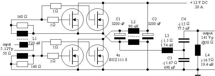

SEPP_PA.gif by DF6NM 05/2000
input transformer:
L1: approx. 720uH: 12 + 15 + 15 turns 0.2mm CuL trifilar on ferrite pot core N30, D = 11mm, h = 6mm OL (AL=3200nH)
rf choke, dc blocking caps:
L2: approx. 90uH: 4 + 4 turns 1 mm CuL bifilar on ferrite pot core N30, D = 18mm, h = 11mm OL (AL=5600nH) or D=22mm, h= 13mm OL (AL=7000nH)
C1, C2: 2200 + 1000uF, 25V or 4700uF, 25V, Rs < 2m
WOutput matching filter example:
L3, L4 wound on D = 39mm plastic tube coil formers, using 270*0.05mm litz wire (od=1.5mm), Q > 200
L3: 1.74uH 7 turns, 3 trifilar litz wires in parallel, D = 40mm, l = 27mm
L4: 19.4uH 25 turns, single litz wire, D = 40mm, l = 30mm
C3: 7 * 100nF 400V MKP (50V min)
C4: 5 * 15nF 630V polypropylene (160V min)
Transistors:
BUZ 111 S (Siemens / Infineon): VDSmax = 55 V, RDSon = 8m
W, Ptot = 300 W, Imax = 80 A

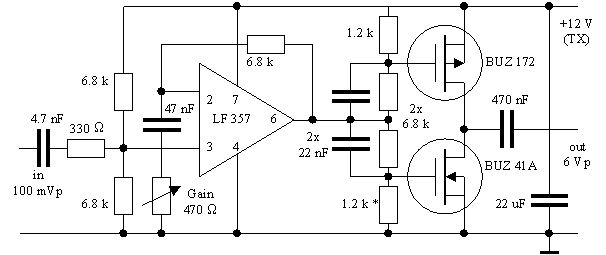
SEPP_Dri.gif by DF6NM 05/2000
* To achieve optimal waveform symmetry adjust one of the gate-source resistors to 50% duty cycle at low drive levels, e.g. 1.2k
W / 2kW.Do not use LF 356 instead of LF357, it is too slow.